I. Introduction
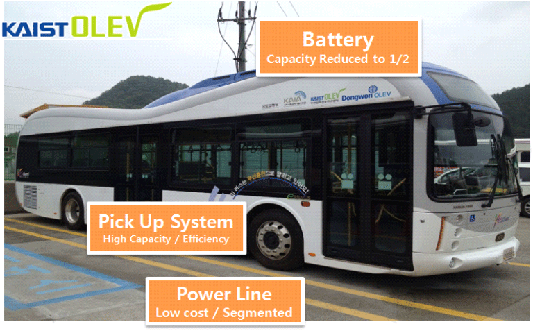
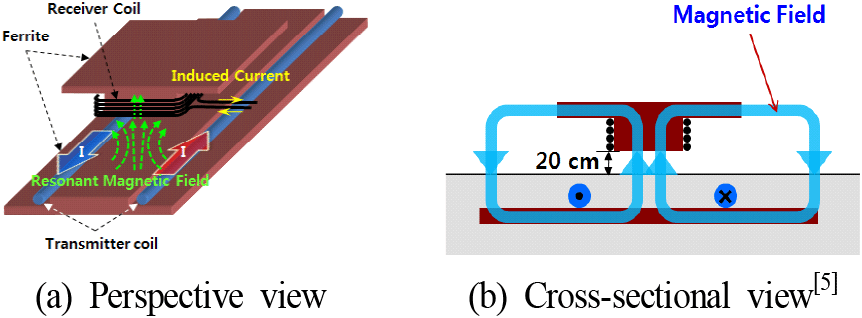
The key elements that differentiate the OLEV (online electric vehicle) from other EVs (electric vehicles) are the wireless power supply system and the power receiving system. For efficient transmission of electric power, resonant coupling between road-embedded transmitter coils and vehicle-embedded pickup modules is applied. With this WPT system, the OLEV (online electric vehicle) successfully receives 100 [KW] power while it is moving as well as when it is stopped on the road, as shown in Fig. 1[5].
For wireless charging while a vehicle is on a road, a road-embedded power supply system and a power receiver system in the vehicle are required. The power supply system can be a part of the public infrastructure of the road or highway system, while the power receiver device, or the pick-up system, can be a part of the vehicle. The pairing of the power supply and the receiver system is tuned to maximize the transmission efficiency through optimized magnetic field shapes and properly tuned resonant frequency.
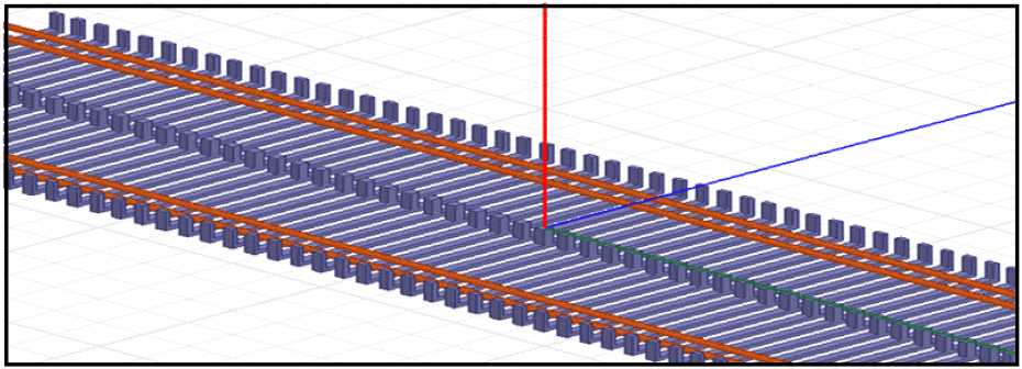
Basically, a transmitter coil and a pick-up module are designed for non-contact power transfer. As shown in Fig. 2, there is a transmitter coil arranged in opposite current directions underneath the road surface, forming a current loop, and magnetic flux is induced around each transmitter coil due to the current in the transmitter coil. Magnetic flux from the two transmitter coils is generated and the pick-up module (=VA, vehicle assembly) receives the vertical magnetic flux using a copper coil around a ferrite core. The windings at the receiver coil in VA generate voltage and current to drive electric the motor and charge the battery. Typically, five pickup modules with 20 KW each are attached at the bottom of the vehicle.
II. New Method for Suppression of Unwanted EMF
It has confirmed that a realistic applicable methods are more important for mass-products of VA and Power lines (GA, ground assembly) than those technically implementable methods. It is noteworthy that ① VA part cannot be applied with any additional shielding techniques, and the old structures should be maintained. ② It need to develop a new way to minimize the manufacture cost while satisfying EMF in GA. GA consists of power cables and ferrite cores. Refer to Fig. 3[5].
A ferrite core’s material are a magnetic iron core. It is used as a transformer or an inductor core by utilizing its high investment rate and low conductivity. The ferrite is a metallic term of steel a solid type based on on α-Fe (alpha iron) with α-cubic crystallography structure. Fig. 3[5] shows a structure in which a lot of unwanted magnetic fields are generated at a non VA area because current flows through all GA regardless of the position of VA[8].
It explains the meaning of the final simulation and looks the results. The simulation tool utilized MawellTM program designed by AnsysTM.
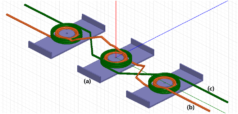
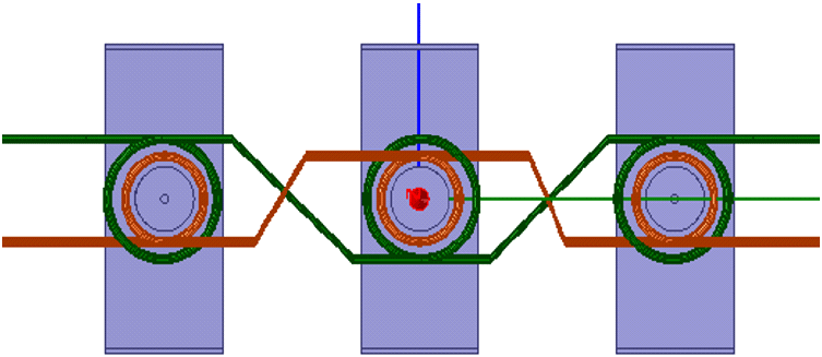
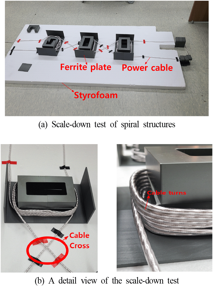
Fig. 4 shows the 「New structures」. Fig. 4(a) means the structure of ferrite-cores, Fig. 4(b) of the orange-color is 「the forward direction of current flow」 and Fig. 4(c) of the green color is 「the reverse direction of current flow」. Fig. 4(a) shows that ferrite cores were used only in the area of VA. So, it can achieve the largest value of LC resonance while increasing magnetic-flux density. It shows only a crossing each other Fig. 4(b) cable and Fig. 4(c) cable in areas without ferrite cores. Although not shown in Fig. 4(b) cables and Fig. 4(c) cables must be interconnected at the ends in order to flow the current.
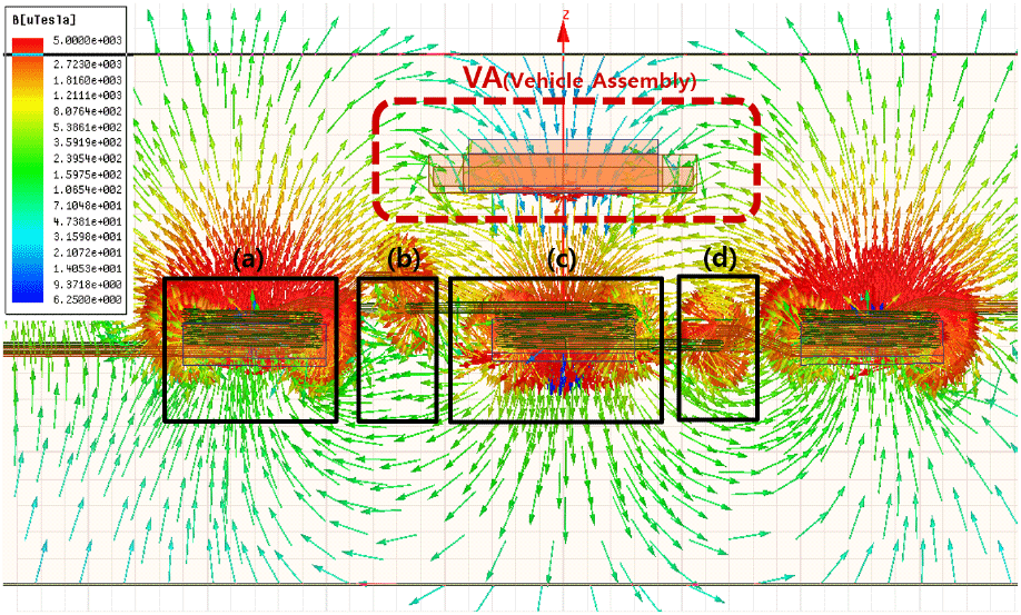
Fig. 5 shows an accurate winding structure of the cable. It shows wound three times around ferrite cores into the forward direction of current flow and Fig. 4(c) shows wound three times around Fig. 4(b) into the reverse direction of current flow. In order to reduce ferrite cores, no uses in area where is no VA. It has an another meaning to cross them each other in areas without ferrite cores. It must be wound into same direction each other betweenthe forward direction of current flow and the reverse direction of current flow. So, those cables must be crossed with each other whenever the number of turns changes. It shows that magnetic fields above 2,723 μT were generated along the crossed power cables. When VA is placed over such as Fig. 6(a), it can be seen that there are induced into VA (vehicle assembly) a very high magnetic field of about 5,000 μT.
When VA (vehicle assembly) is placed over the Fig. 6(c), it can be seen that 5,000 μT are induced into the vehicle assembly, the gap between VA and GA is almost saturated into a magnetic field. It means that the spiral structure is a key design factor to create LC resonance between the ground assembly and the vehicle assembly. What creates well LC resonance means also that EMF could be minimized. In Fig. 6(d), It confirms that the magnetic field is significantly reduced at the point where the cable is crossed. The voltage is 550 V and the variable current is 54~56 A, The frequency is 20 kHz.
In Fig. 7(a), it shows the scale-down real condition of spiral structures. It consists of the same structure of the simulation type in Fig. 4, and the test environment is configured not to be affected by ambient noises. The bottom surface is laid with a StyrofoamTM which is not affect ferrite plates (Fig. 8).
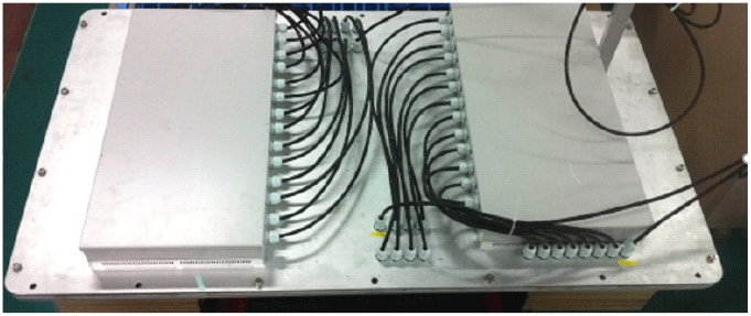
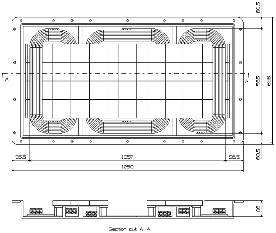
In case of the vehicle assembly shown in Fig. 9, it is the existing structure. That is to say again, it has no changed anything. The dimension of the vehicle assembly in this scale-down real test is designed to Fig. 9.
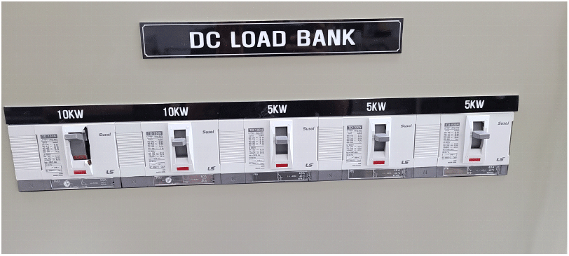
It is very difficult to implement experimentally because the battery size and capacity of the actual bus are too large. But this scale-down system size can use as a charging of one VA (vehicle assembly). The capacity of one VA is almost 33 KW. The real capacity of electric bus is mainly 100 KW, uses 3 VAs. Under this reason, the DC load bank is applied in stead of real vehicle batteries. The max. capacity of DC load bank is 35 KW. In order to protect the function of DC load bank and to provide a stable power, this scale-down test is limited the output power as 30 KW, which is the rated power of the DC load bank (Fig. 10).
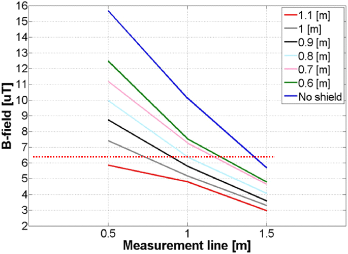
The results of the scale-down real test is the graph shown in Fig. 11.
The width of electric bus is at least 2,495 mm (≈2.5 m), basically the 1.1 m separation distance of VA is more than satisfactory. The 1.1 m separation satisfies well of the legal limitation, 6.25 μT[4]. The value was 5.9 μT show in Fig. 11.
In addition, The previous WPT efficiency was almost 85 percent. Of course, this is by no means low efficiency in high power WPT. However, this new structure provides better improvement of WPT efficiency. The reason is that EMF is improved by minimizing leakage fields. The leakage fields was induced well into VA, as shown by the comparison among Fig. 6(b), Fig. 6(d) areas without VA and Fig. 6(c) area with VA in Fig. 6. The impeoved efficiency was 93.7 % and incread 13.7 %P than the previous it (80 %). In conclude, it shows that the method of minimizing leakage fields improves the efficiency more than the complex application of EMF protecting methods.
III. Conclusion
This new structure revealed that EMF can be further suppressed without structural changes in vehicle assembly (VA) and the efficiency can be also improved only by the re-designed ground assembly (GA) of the previous E-type structure. It proves that the scale-down real test is satisfied the 6.25 μT[4] even with a separation distance of 1.1 m from the center of ferrite cores structures at 30 KW output. In fact, it proves that the scale-down real test satisfies more enoughly EMF limits than the simulation. Also, it reveals that the efficiency improved to about 13.7 %P than the previous structure.

