I. Introduction
The rising demand for systems that allow simultaneous transmission and reception is evident in advanced wireless communication, providing advantages such as higher data throughput and efficient spectrum utilization[1]. A key challenge, however, is achieving high isolation between the transmitter and receiver to mitigate self-interference. Furthermore, for communication at higher frequencies high-gain antennas are essential to reduce free-space attenuation, which reaches its maximum at 60 GHz due to oxygen absorption (15 dB/km). A single-ended fed 60 GHz 2×2 SIW array achieved 7~11.9 dBi gain but had a suboptimal −7 dB reflection coefficient for 54.5~62 GHz[2].
This paper introduces a cavity-backed elliptical slot antenna using a single-layer SIW structure. The in-band full-duplex communication scenario is evaluated through simulations using two modules. For performance validation the proposed 2×2 antenna array integrated with a 1×4 SIW-based power divider is fabricated. The fabricated prototype achieves a 16.61 % reflection bandwidth (S11<−10 dB) with a peak gain of 9.7~11.5 dBi, making it suitable for 2-channel in-band full-duplex mm-Wave communication.
II. Antenna Geometry and Operating Principle
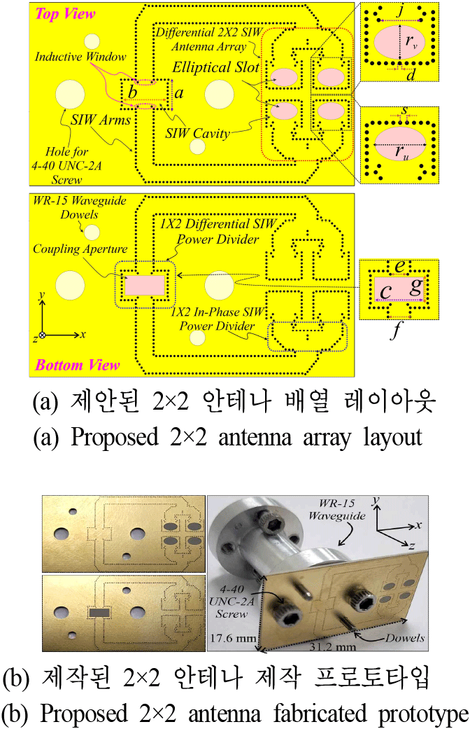
The proposed antenna, shown in Fig. 1 with parameters in the caption, utilizes a single layer of Taconic RF-60TC substrate (εr=6.15, tanδ=0.002 @ 10 GHz) with a thickness of 0.51 mm. The SIW arms and cavity are constructed by connecting the top and bottom metal layers through series of via, with each via having a diameter d and spacing s, ensuring s ≤ 2d to maintain radiation loss below −0.06 dB across the V-band. An elliptical slot with major and minor radii rᵤ and rᵥ is etched into the top metal of the SIW cavity, with dimensions initially chosen to support the fundamental eigenmode of the resonant cavity and further optimized using full-wave EM simulation in HFSS for better performance. Fig. 2 shows design evolution steps for the proposed 2×2 differential-fed antenna array.
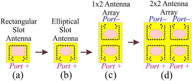
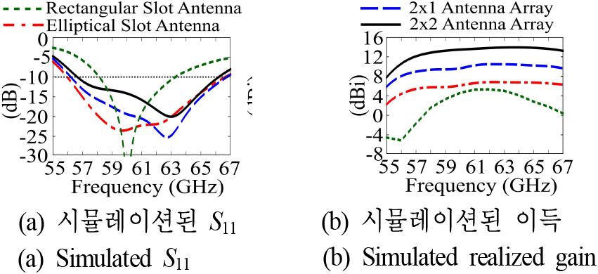
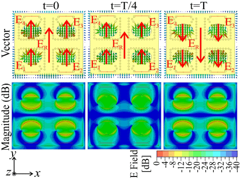
The initial design featured an SIW-based cavity-backed rectangular slot antenna (Fig. 2(a)), which exhibited a narrow bandwidth with a single resonance at 60 GHz (Fig. 3(a)). By modifying the slot into an elliptical shape with major and minor radii rᵤ and rᵥ (Fig. 2(b)), multiple resonant modes were excited, resulting in a wider bandwidth (Fig. 3(a)). The elliptical slot’s smooth aperture field distribution and lower Q-factor improved radiation efficiency and impedance matching, leading to enhanced gain across the extended bandwidth (Fig. 3(b)). For further gain improvement, a 1x2 array was designed by vertically mirroring the single element with 3.25 mm spacing (Fig. 2(c)), and differential out-of-phase excitation ensured broadside radiation, boosting gain by over 3.5 dB (Fig. 3(b)). Finally, a 2×2 differentially fed array was developed with horizontal and vertical element spacing of 4.5 mm (0.9 λ at 60 GHz) and 3.25 mm (0.65 λ at 60 GHz), respectively (Fig. 2(d)). The horizontal elements were fed in-phase, while the vertical elements were fed out-of-phase. The optimized array achieved S11<−10 dB across 56.7~66 GHz and a realized gain of 11.75~13.9 dBi, as shown in Fig. 3(b). The electric field distribution at 60 GHz, depicted in Fig. 4, illustrates the proposed array operating principle. Differential excitation aligns the electric field in the broadside direction, optimizing radiation, with stronger intensity observed along the elliptical slot’s edges. As the phase progresses from 0° to 180°, the field direction reverses, confirming linear polarization.
III. 1×4 SIW-based Differential Power Divider
To excite the proposed 2×2 differential antenna array, a 1×4 SIW-based differential power divider was designed on the same Taconic RF-60TC substrate. Energy is coupled from the WR-15 waveguide to the SIW cavity through an aperture in the ground plane, with dimensions matching those of the WR-15 waveguide. It is then transferred to the SIW arms via an inductive window, whose width is chosen to support TE10 mode propagation, as shown in Fig. 5(a) by the electric field distribution at 60 GHz. An E-plane T-junction generates differential signals, which are further divided by 1×2 in-phase SIW power dividers, producing four arms. Two of these have in-phase signal and other two have out-of-phase, ensuring optimal excitation of the 2×2 array.
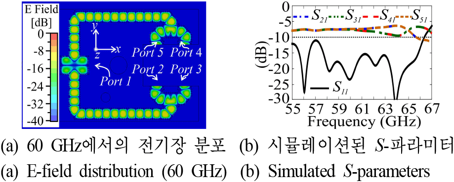
Fig. 5(b) shows that the optimized power divider achieves a reflection coefficient below −10 dB across 57~64 GHz, with a transmission coefficient of approximately −7.4 dB at 60 GHz. Phase analysis confirms accurate signal distribution, with ports 1 and 2 in-phase and ports 3 and 4 showing a 180° phase shift, ensuring precise differential excitation.
IV. In-Band Full-Duplex Communication
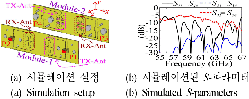
Fig. 6(a) depicts an in-band full-duplex communication setup in HFSS software with Module 1 and Module 2 placed face to face, each equipped with TX and RX antennas. Antenna 1 (TX) in Module 1 transmits to Antenna 3 (RX) in Module 2, while Antenna 4 (TX) in Module 2 transmits to Antenna 2 (RX) in Module 1. The TX-RX spacing within each module is 10 mm (~2 λ at 60 GHz), and the inter-module distance is 5 mm (~1 λ at 60 GHz).
Fig. 6(b) shows S-parameters, demonstrating excellent performance. Reflection coefficients (S11=S44) are well-matched, and isolation (S21=S34) is −22.6 dB, ensuring minimal interference. Transmission coefficients (S31=S24) achieve −6.4 dB at 60 GHz, with an overall reflection coefficient of −9 dB, both suitable for this application. These results highlight the antenna’s potential for in-band full-duplex communication in the 60-GHz band.
V. Experimental Results for Proposed 2×2 Antenna Array
For performance validation, the proposed 2×2 differential antenna array with feeding network was fabricated and subsequently tested for reflection coefficient and far-field radiation as shown in Fig. 7(a) and Fig. 7(b) respectively.
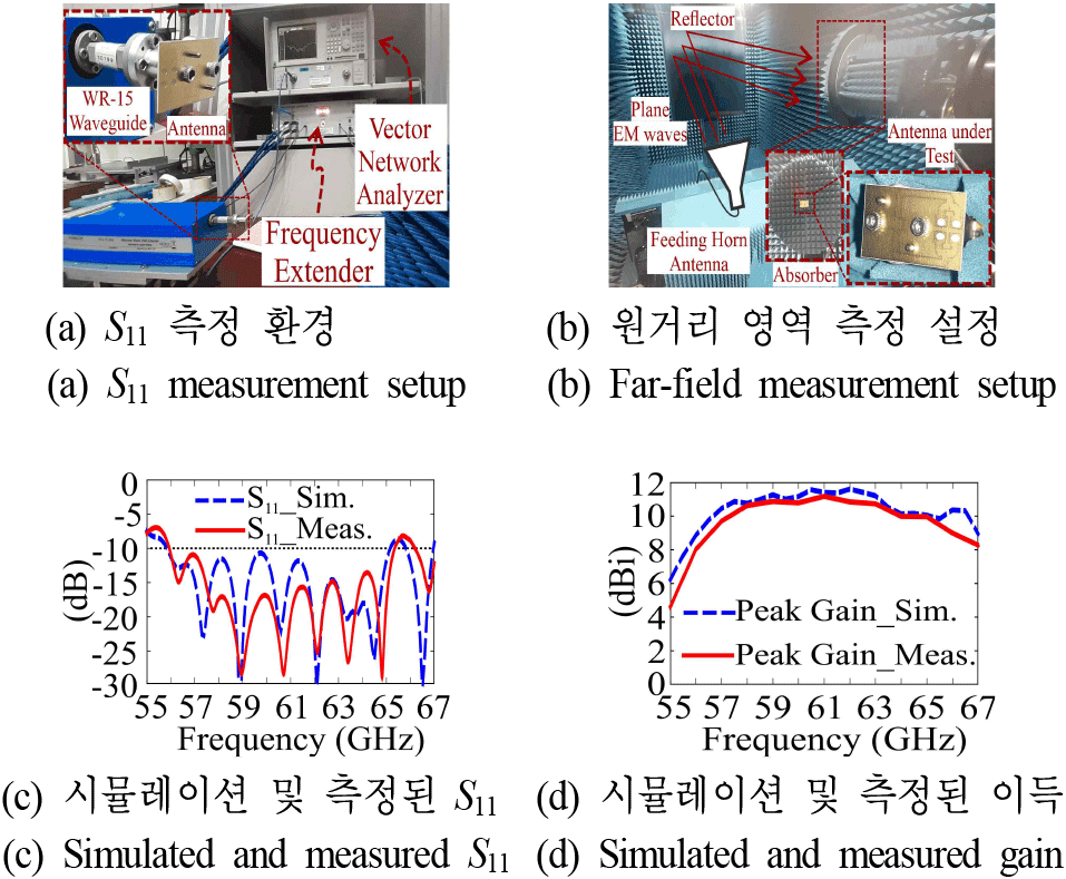
The measured reflection coefficient bandwidth was 16.61 % (S11<−10 dB) from 56 to 65.3 GHz, closely corresponding the simulated 18.73 % bandwidth (55.85~65 GHz) as shown in Fig. 7(c). The measured gain ranged from 9.7 dBi to 11.5 dBi, consistent with the simulated range of 10.45 dBi to 11.6 dBi (Fig. 7(d)). Resonance points observed in S11 curve and gain reductions were caused by feeding network losses, fabrication tolerances, and changes in substrate permittivity and loss tangent, as per Debye model.
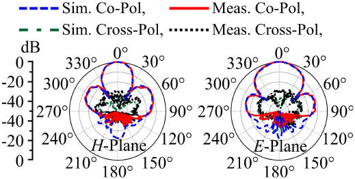
Fig. 8 shows normalized radiation patterns at 60 GHz along the H-plane (xz-plane) and E-plane (yz-plane), with strong agreement between measured and simulated results. The antenna also achieves a broadside cross-polarization level below −20 dB. The sidelobe level can be further reduced by decreasing inter-element spacing to mitigate interference in in-band full-duplex communication.
VI. Conclusion
A compact 2×2 SIW-based elliptical slot antenna with a differential feeding network is designed and fabricated on a single-layer Taconic RF-60TC substrate. The antenna achieves a wide reflection bandwidth of 16.61 % (56~65.3 GHz for S11<−10 dB) and a gain of 9.7~11.5 dBi. In-band full-duplex communication is evaluated through simulations at a 5 mm (~4 λ) spacing. The differential feeding ensures symmetric broadside radiation, low sidelobes, and improved inter-element isolation, making it suitable for 60-GHz two-channel in-band full-duplex communication.


